4dof-mearm-robot
4-DOF MeArm Robot
Building and programming a 4 degree of freedom robotic arm (MeArm Robot Kit)
Link :- 4-dof-mearm-robot
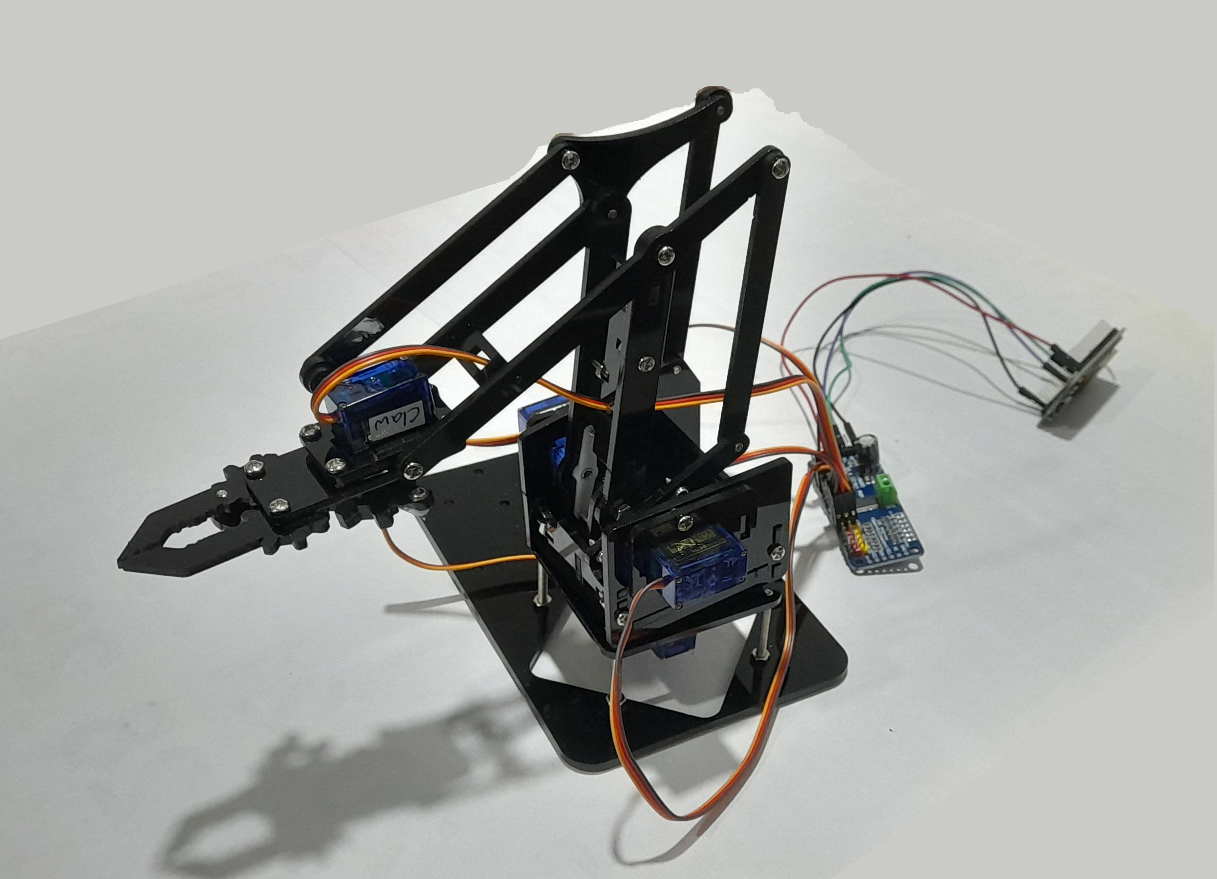
Hardware
List of hardware (with links)

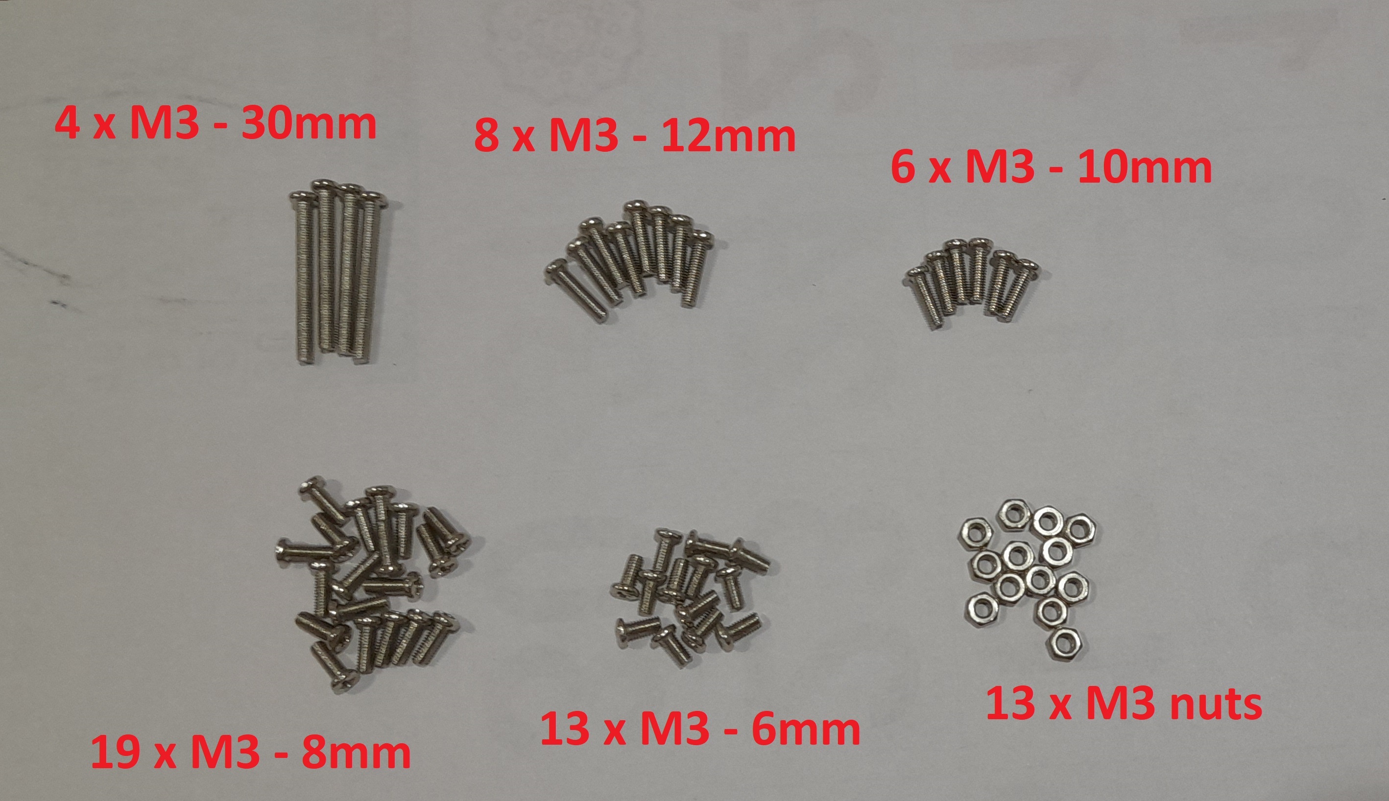
The following fasteners are included in the MeArm Robot kit :
- 4pcs x M3 - 30mm
- 8pcs x M3 - 12mm
- 6pcs x M3 - 10m
- 19pcs x M3 - 8mm
- 13pcs x M3 - 6mm
- 13pcs x M3 hex nuts
Calibrating Servo Motors
Servo Motor Pinout
- Brown : Ground
- Red : +5V Supply
- Orange : Signal (PWM)
The servo motor position changes from $0^0$ to $180^0$ depending on the duty cycle of the PWM signal given to the Orange wire.
The duty cycle corresponding to minimum and maximum position must be found during the calibration process.
PCA9685 Driver
Connect the Motor driver module to the ESP32 for testing. Tutorial for connecting the module to an Arduino is given here
Connect the Module to the ESP32 as follows
| ESP32 Pin | Module Pin |
|---|---|
| 3V3 | VCC |
| GND | GND |
| D22 | SCL |
| D21 | SDA |
The power for the servo motors must be given through an external power source to the V+ and GND terminals. Connect this to a 5V power source capable of sourcing ~2A current
Calibration process
The duty cycle corresponding to minimum and maximum servo positions was found using an analog potentiometer with the “servo_test” code.
Servos were set to the required position using the “servo_calib” code.
Assembly Process
Several assembly tutorials available online. This kit differs slightly from most other commonly avaliable kits. Some linkages are missing. This is a video tutorial for this exact kit.
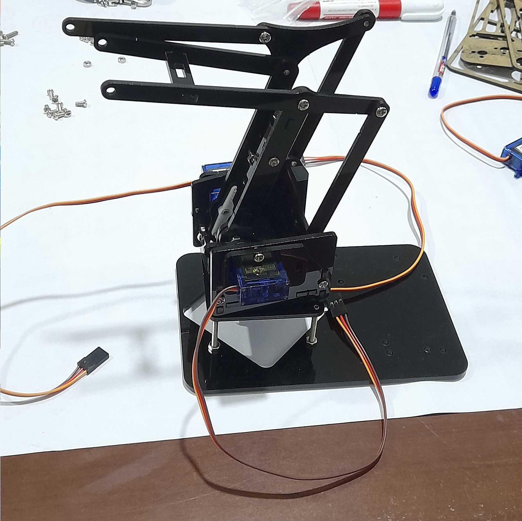
Take care during assembly as the acrylic parts (particularly the servo motor holders) are fragile.
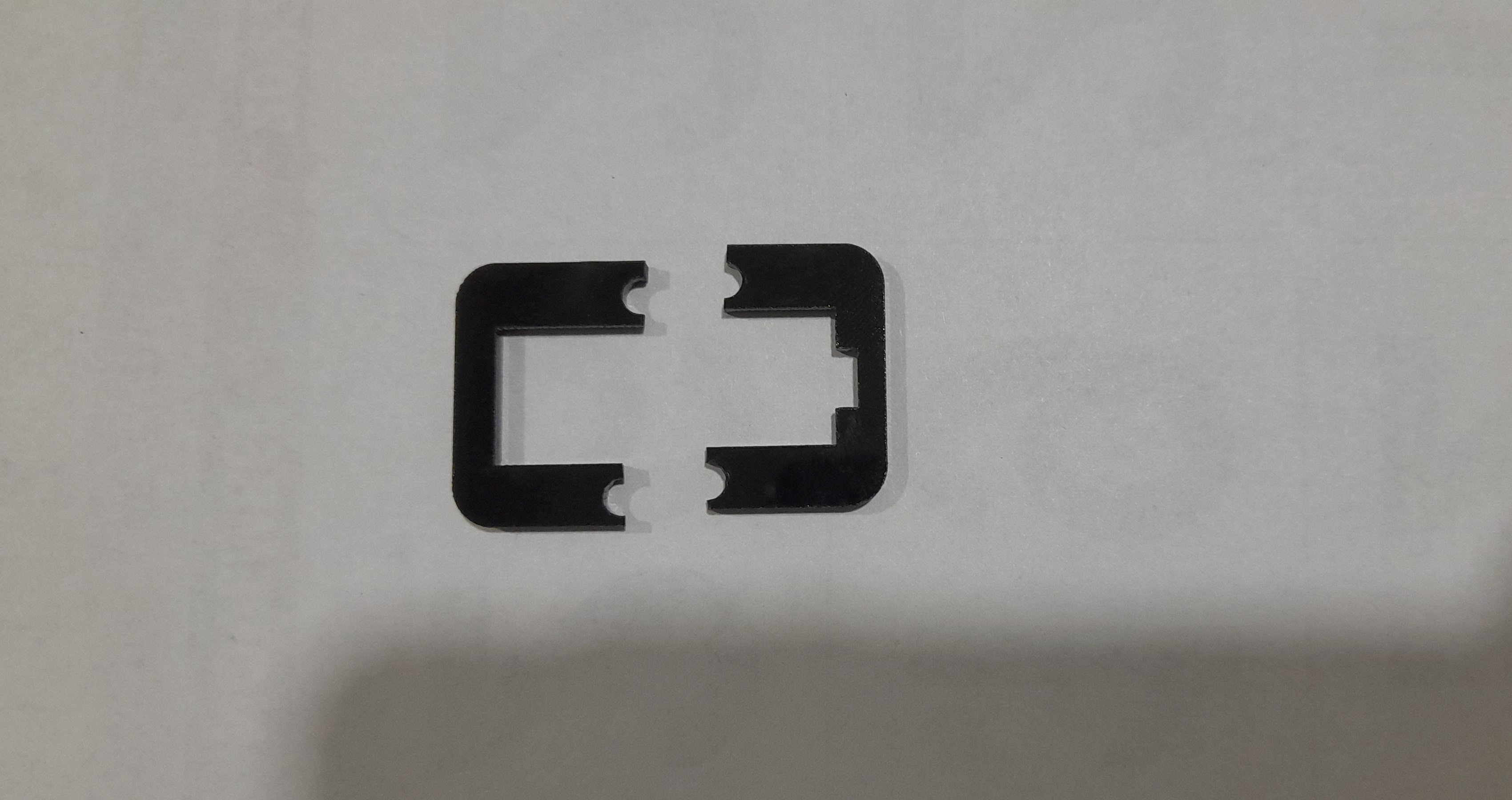
Can be mended using superglue, but are prone to breaking again.
Dimensions
Accurate measurements of the dimensions are essential for proper calculation of inverse and forward kinematics.
The dimensions of the kit used in the this project are given below.
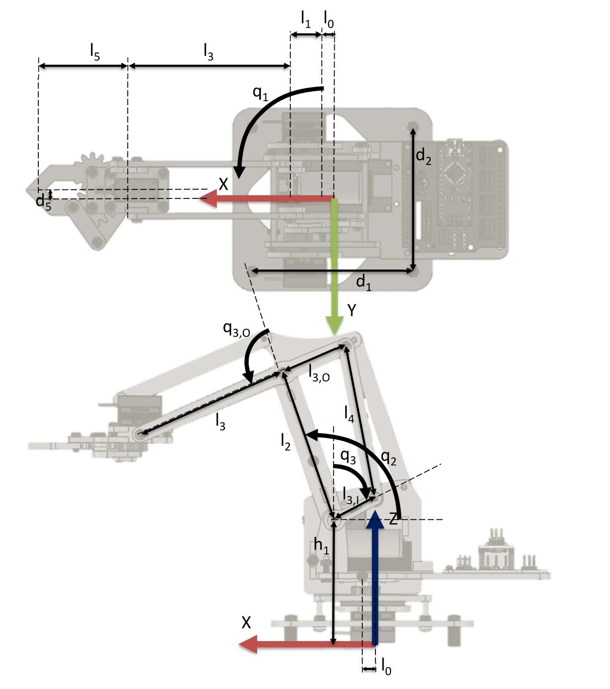
| Paramter | Value (mm) |
|---|---|
| $l_0$ | 0 |
| $h_1$ | 64 |
| $l_1$ | 15 |
| $l_2$ | 80 |
| $l_3$ | 80 |
| $l_{3I}$ | 35 |
| $l_{3O}$ | 35 |
| $l_4$ | 80 |
| $l_5$ | 65 |
| $d_5$ | 5 |
Before calculating configurations using inverse kinematics, the angles of the servo motors must be verified. This can be done by setting all servos to $90^0$ and checking with the given diagram above.